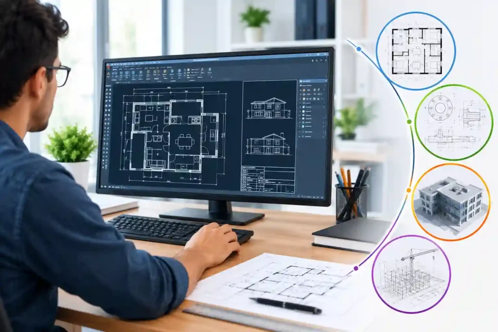
This document talks to those readers who are interested in knowing about 2D CAD drafting. It considers 2D CAD drafting as the digital formation of precise, scaled technical drawings on an X-Y plane across architecture, engineering, and manufacturing. It provides detailed information about main features, discipline-specific applications, 2D conversion, quality checklists, and comparison of 2D and 3D CAD workflows.
It provides solutions to the problems of readers searching target topics or keywords, like 2D CAD drafting, 2D CAD vs 3D CAD, or 2D CAD conversion. It helps readers find solutions by:
- guiding them on selecting suitable software,
- executing correct conversions,
- applying standardization checklists to avoid design errors,
- assessing when to outsource drafting services to maintain productivity
2D CAD substitutes manual drafting tools with software that facilitates architects, engineers, manufacturers, contractors, and fabricators in communicating geometry, dimensions, notes, and intent. 3D modeling has become more popular in the industry these days. However, 2D documentation is not obsolete, because 2D standardized drawing sheets are still required to issue plans, sections, details, schematics, shop drawings, permit sets, and official records successfully.
What Is 2D CAD Drafting?
In practice, this drafting method turns design information into scaled linework and annotations describing an object, building, system, or component using width and height. Autodesk defines 2D CAD as a digital platform for creating precise technical drawings and plans across architecture, engineering, and manufacturing. Professional drafting controls coordinates, layers, dimensions, symbols, text, hatching, references, and plotting standards.
ISO 128-1:2020, confirmed current by ISO in 2026, sets general representation principles for manual and computer-based technical drawings in mechanical engineering, construction, architecture, and shipbuilding. That standardization supports reliable 2D CAD drawings across multidisciplinary and international projects.
Core Features of 2D CAD Drawings
Modern CAD platforms combine accuracy with repeatable controls:
- Precision geometry for lines, arcs, circles, polylines, coordinates, offsets, and intersections.
- Layers that separate disciplines, systems, objects, line weights, colors, and visibility.
- Dimensions and annotations for sizes, levels, tolerances, notes, callouts, and references.
- Reusable blocks for fixtures, equipment, symbols, and title blocks.
- Hatching and fills for materials, cut surfaces, or zones.
- Layouts and viewports that organize scaled views into issue-ready sheets.
- DWG and DXF workflows for exchange, revision, archiving, and coordination.
Autodesk’s AutoCAD guidance also identifies layers, annotation, dimensions, blocks, layouts, and precision tools as foundations of efficient documentation.
Different Types of 2D CAD Drafting
Requirements vary by discipline and deliverable:
Architectural drafting: floor plans, ceiling plans, elevations, sections, schedules, and construction details.
Civil drafting: site plans, grading, road alignments, profiles, utility layouts, drainage, and infrastructure details.
Structural drafting: foundations, framing plans, reinforcement details, steel details, sections, and connections.
Mechanical drafting: machine parts, assemblies, fabrication details, tolerances, and manufacturing documentation.
Electrical drafting: single-line diagrams, lighting layouts, power plans, cable routes, and control schematics.
MEP drafting: coordinated mechanical, electrical, plumbing, fire-protection, and building-services layouts.
These specialties show why professional 2D CAD drafting services require software skill plus discipline knowledge. A neat drawing can fail when design intent or CAD standards are misunderstood.
Uses and Applications of 2D CAD Drafting
2D drafting is used whenever a project needs controlled technical documentation rather than only visual presentation. Typical applications include construction drawings, planning submissions, tender documents, as-built updates, shop drawings, equipment layouts, fabrication sheets, maintenance records, schematic diagrams, land-development plans, and redline incorporation.
The U.S. Bureau of Labor Statistics reported about 192,100 drafting jobs in 2024, including 110,500 architectural and civil drafting jobs. BLS projects roughly 16,200 openings per year from 2024 to 2034, mostly for replacement needs. The figures show drawing expertise remains important as CAD, BIM, and automation improve productivity.
For many organizations, 2D CAD drawings are the communication layer between designers, reviewers, contractors, fabricators, and field teams, supporting pricing, approvals, fabrication, installation, inspection, and handover.
Key Benefits of 2D CAD
Key benefits of 2D CAD include speed, precision, standardization, and accessibility. Teams can revise geometry without recreating entire sheets and reuse approved content.
Key advantages include:
- Faster revisions, copying, scaling, and sheet updates.
- Accurate dimensions and coordinate-based geometry.
- Standardized layers, title blocks, text, symbols, and plotting.
- Easier exchange with consultants, contractors, and vendors.
- Lower file complexity than many model-heavy workflows.
- Practical output for permits, fabrication, construction, and records.
- Efficient reuse of typical details and standard blocks.
Another of the benefits of 2D CAD is selective communication: teams can control information by layer and issue only what a reviewer or trade needs.
Limitations and Cons of 2D CAD
2D documentation has limitations. Separate views must be coordinated carefully, so a plan change may require updates to elevations, sections, details, or schedules. Complex geometry is harder to visualize, and interference between systems is less obvious than in coordinated 3D environments.
Other disadvantages include duplicated information, inconsistent revisions, incorrect layers, missing references, and repetitive-editing errors. Standards, checking procedures, and revision control are therefore essential.
2D CAD vs 3D CAD: Which Is Better?
The 2D CAD vs 3D CAD decision should be based on the deliverable, not which technology appears newer. 2D is often faster for straightforward plans, details, schematics, and legacy documentation. 3D is stronger when spatial visualization, clash detection, simulation, complex geometry, quantities, or model-based coordination are central.
Neither workflow must replace the other. Many engineering teams coordinate geometry in 3D and issue controlled 2D sheets for approvals, fabrication, construction, or operations.
Cost and project maturity also matter. A small modification may not justify a complete model, while a multidisciplinary facility may face coordination risk if it relies only on 2D. The best 2D CAD vs 3D CAD strategy matches information depth to project need.
What Is 2D CAD Conversion?
2D CAD conversion transforms legacy drawings or non-editable files into structured CAD data. Inputs can include paper drawings, scans, PDFs, TIFF images, marked-up sheets, old CAD formats, or exported model views. The goal is not merely tracing lines; it is rebuilding usable geometry with correct layers, dimensions, text, blocks, scales, and organization.
Good 2D CAD conversion includes source checking, consistent naming, and verification of dimensions. It is common in archive digitization, renovation, facility records, tender documentation, and modernization of historical drawing libraries.
For high-volume programs, outsourced CAD conversion can reduce the burden on in-house engineers while creating an editable archive. Unclear geometry or dimensions should be flagged, never invented.
Choosing Simple 2D CAD Software
The best simple 2D CAD software depends on file compatibility, drawing complexity, collaboration, licensing, and client standards. Basic work may require only geometry tools, layers, dimensions, text, blocks, hatching, snapping, and dependable PDF output.
However, simple 2D CAD software is not automatically suitable for professional production. Confirm DWG or DXF compatibility, external-reference handling, plotting consistency, fonts, units, layer controls, and clean file exchange with consultants.
Choose simple 2D CAD software for straightforward drafting and learning, but use proven professional workflows when drawings support construction, manufacturing, regulated approvals, or multidisciplinary coordination.
When to Use 2D CAD Drafting Services
Organizations outsource 2D CAD drafting services when internal teams are overloaded, drawing backlogs must be converted, deadlines require extra production capacity, or specialized drafting standards are needed. Offshore delivery works well for repeatable packages, redline updates, standard detailing, CAD cleanup, as-built documentation, and conversion programs.
IMES supports offshore 2D CAD drafting services for architectural, civil, structural, mechanical, electrical, and infrastructure documentation. A strong offshore partner should offer disciplined layer management, template compliance, revision tracking, drawing checks, secure file handling, and communication with the engineering lead.
A reliable workflow starts with sample sheets, standards, naming conventions, deliverables, checking responsibility, and turnaround priorities. IMES also supports 2D CAD conversion and coordinated CAD drawings, allowing client engineers to focus on design, reviews, and project management.
Quality Checklist for Professional 2D Deliverables
Before issue, a competent checker should confirm:
- Scale, units, coordinates, and sheet references are correct.
- Dimensions match approved design information.
- Layers, line weights, text, symbols, and hatches follow standards.
- Plans, sections, elevations, and details are consistent.
- Xrefs, fonts, and linked files are properly packaged.
- Revisions, statuses, and drawing numbers are controlled.
- PDFs plot correctly at the intended sheet size.
- No unsupported assumptions were introduced.
This discipline separates basic CAD operation from dependable technical drafting.