Transportation agencies and design firms keep tightening up QA/QC because road projects are costly to fix once construction starts. Across many DOT reviews and industry lessons learned, the same subjects show up: small geometry differences, outdated sheets, and coordination gaps can cause rework, delays, and change orders. That’s the reason that road design software has become a nucleus of modern delivery, specifically when teams require fast revisions, consistent quantities, and clearer constructability before bids go out.
What Does Road Design Software Means in Modern Civil Engineering Road Design
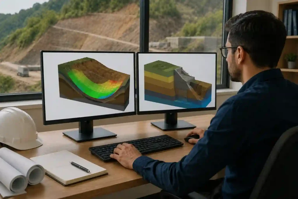
In today’s civil engineering road design, “software” is not just drawing lines. It generally means a 3D, rules-based workflow that links together terrain surfaces, alignment geometry, profiles, cross-sections, and quantities so that changes reproduce consistently.
A conventional approach begins with a digital terrain model (DTM) or surface built from survey, lidar, or drone photogrammetry. Engineers then state horizontal alignment (the road centerline geometry in plan) and vertical alignment (grades and vertical curves in profile). From there, the design converts “parametric”: the model uses templates (assemblies) and rules to create a continuous corridor instead of manually redrawing every section.
Key terms (in plain language):
- Alignment: The road’s plan path view, that includes tangents and curves, set by design speed and constraints.
- Profile: The elevation path alongside the alignment (grades and vertical curves).
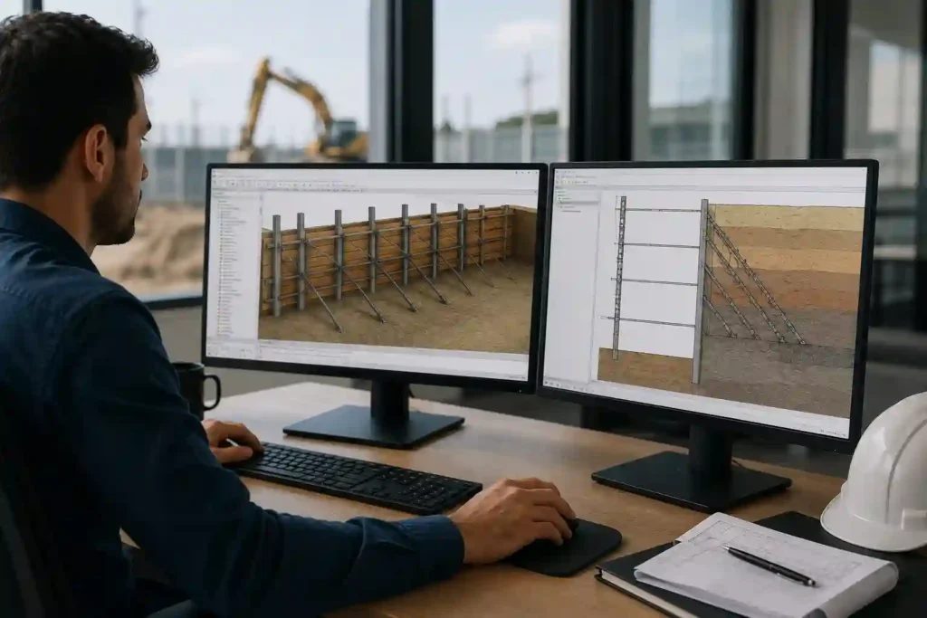
- Cross-sections: Portions of the road showing lanes, shoulders, side slopes, and drainage features at stations.
- Corridor model: A 3D “extrusion” of cross-section templates along the alignment and profile.
- Superelevation: Banking on curves to match speed and safety needs, often driven by standards and friction factors.
- Earthwork quantities: Cut/fill volumes computed from existing vs proposed surfaces.
What Traditional Drafting Looks Like Today
Conventional drafting isn’t “old school hand drawing” anymore. It’s normally 2D CAD creation (and sometimes light 3D) that focuses on plan and profile sheets, standard details, and manual coordination between drawings.
In a drafting-heavy workflow, geometry is often generated as polylines and annotated with dimensions and labels. Profiles may be generated from separate tools or spreadsheets, and cross-sections can be produced but may not remain fully linked to design rules. When a change happens e.g. a curve radius adjusts, or a profile grade shift, the team repeatedly rechecks multiple sheets, updates stationing, and revises quantities through a combination of manual steps and semi-automated tools.
Conventional drafting can still be effective when scope is small, data is limited, or deliverables are accurately 2D. But it becomes difficult to handle when revisions are recurrent and multi-discipline coordination is intense.
Road Design Workflow Compared: from Survey to Sheet Sets
Both strategies observe similar engineering logic, but they treat change propagation and quantities very differently.
Road Design Workflow in a Road Design Software Corridor Model
Most teams using road design software adhere to a model-first flow where geometry and quantities stay coupled:
- Import survey/lidar and make an existing ground surface (DTM).
- Determine design criteria (design speed, lane/shoulder widths, max grades, sight distance).
- Build horizontal alignment and stationing.
- Make vertical profile and vertical curves.
- Develop typical sections (templates/assemblies) for lanes, shoulders, medians, and side slopes.
- Apply superelevation rules and widening where required.
- Create a corridor model and proposed surface.
- Calculating earthwork quantities and material takeoffs from surfaces.
- Produce plan/profile sheets, cross-sections, and tables that stay linked to the model.
- Go on QA/QC checks (geometry standards, slope limits, clash checks, constructability review).
Traditional Drafting Workflow in 2D CAD
A drafting-led workflow can be fast at beginning, but more manual to continue:
- Importation of survey basemap and reference control points.
- Draw plan geometry (centerline, edges, right-of-way) and annotate.
- Craft profile drawings via separate tools or manual profile generation.
- Prepare typical sections and details from standards.
- Create cross-sections as separate outputs (often less “live linked”).
- Estimation of quantities using spreadsheets, separate surfaces, or manual methods.
- Update sheets and tables manually after geometry modifications.
- Accomplish coordination checks through markups and overlay comparisons.
Accuracy, Efficiency, and Collaboration
Here’s where the difference becomes evident on real projects.
Accuracy and Error Reduction
When geometry and quantities are connected, less inconsistencies slip through. With road design software, a profile change can automatically revise cross-sections, corridor surfaces, and quantities, so long as the model is properly set up and governed.
Traditional drafting can still be perfect, but it trusts more heavily on disciplined manual checking, clean layer standards, and rigorous revision control. The risk increases with each revision cycle and each additional discipline involved.
Pros and Cons at a Glance
Pros of Road Design Software
- Fast revision cycles because changes propagate through profiles, sections, and quantities.
- Reliable quantity confidence for earthworks and materials.
- Stronger partnership when multiple teams work from the same model.
- Easy to scale for long corridors and complex junctions.
Cons of Road Design Software
- Upfront training time and procedure setup.
- Needs data governance (templates, standards, naming, version control).
- May be overkill for small, low-risk projects.
Pros of Traditional Drafting
- Lower obstacle to entry for basic plan production.
- fast for small projects with stable geometry.
- Acquainted workflow for many teams and reviewers.
Cons of Traditional Drafting
- Higher organization effort across sheets and disciplines.
- More time to be spent on rechecking quantities after changes.
- Revision risk grows with project size and complexity.
Tools Engineers Actually Use: Road Designing Software, Road Design Program Options, and Legacy Inroads Software
Engineers use a combination of platforms depending on client standards, region, and team maturity. “Road designing software” often means to combined civil design suites that support surfaces, alignments, corridors, sections, and plan production in one ecosystem.
What a Road Design Program Essentially Does
A road design program usually supports:
- Geometric design making (alignments, profiles, vertical curves).
- Template-based cross-sections and corridor creation.
- Superelevation and widening computations based on criteria.
- Automated labeling, tables, and sheet set creation.
- Quantity takeoffs and reporting from suggested surfaces.
A well-configured road design program works as a change-management engine: it decreases redraw time and helps teams to focus on engineering decisions, and not repetitive drafting.
Where Inroads Software Fits Today?
Inroads software is repeatedly discussed as a legacy Bentley workflow that many organizations used for years, specifically where established standards and historical project libraries exist. In modern practice, inroads software context usually concerns in two ways: (1) migration of older project data and standards, and (2) compatibility prospects where clients still like to reference established Bentley-based deliverables.
The Bigger Platform View: Road Infrastructure Software
As projects become multi-discipline, “road infrastructure software” can suggest broader platforms that relate roadway geometry with drainage, utilities, structures, GIS, and asset data for lifecycle managing. This is where model-based data facilitates long-term operations, not just design and construction.
Costs, Licensing, Training, and ROI of Road Design Software
Cost is seldom limited to just “license price.” The real financial impact results from productivity, risk decline, and how well the tool supports the project delivery model.
Typical Cost Buckets to Compare
| Cost area | road design software approach | Traditional drafting approach |
|---|---|---|
| Licensing | Subscription or enterprise seats; higher direct software spend | Lower direct spend if using basic CAD |
| Training | Higher upfront learning curve; needs standards/templates | Lower training for basic drafting tasks |
| Production | Faster revisions; stronger quantity automation | More manual rework and checking |
| Risk | Lower risk of sheet/model mismatch when governed well | Higher revision risk on complex projects |
| ROI | Stronger on long corridors or frequent design changes | Stronger on small, stable-scope jobs |
Training and Governance
Adopting road design software successfully usually needs:
- Standard templates and assemblies that are aligned with client specs.
- A naming/versioning system to stop “model drift.”
- A QA/QC checklist that contains model health, not only sheet checks.
- Time for pilot projects before high-stakes delivery.
ROI Logic That Executives Care About
ROI have a tendency to show up in:
- Less redesign loops because geometry updates automatically.
- More consistent earthwork quantities, reducing budget uncertainty.
- Better cooperation, lowering coordination time between roadway, drainage, utilities, and structures.
- Decreased claims risk, because design intent and revisions are clearer.
For long corridors or design-build schedules, the financial case can be insistent: fast revision cycles protect timelines and decrease the chance of late-stage design changes landing during construction.
Where Road Infrastructure Software Changes the Business Case
A second-layer decision is whether a platform beyond pure roadway geometry is necessary. Road infrastructure software becomes beneficial when the owner wants data continuity for asset managing, maintenance planning, and future updates.
Instead of considering drawings as the final product, teams handle the model and associated data as the deliverable. That can influence long-term infrastructure investment decisions by expanding transparency on quantities, materials, and lifecycle impacts.
Best-Fit Scenarios and Real-World Use Cases
Use cases help in clarification regarding what’s “best,” because the answer depends on scope, risk, and delivery constraints.
- Rural road rehab with limited data: Traditional drafting can work best if geometry is simple and revisions are minimal.
- Urban arterial widening with utilities: Model-based workflows facilitate coordinate clashes, staging, and frequent design changes.
- Highway interchange redesign: 3D corridors and superelevation logic decrease errors across complex geometry.
- Mountain roads with safety constraints: better sight distance checks, grading control, and constructability validation support protected designs.
- Fast-track design-build: road design software assists manage revisions under tight timelines.
- Agency projects with digital delivery: A structured model workflow can comply with evolving digital submission and QA expectations.
How to Choose the Right Approach
Use this checklist to determine what fits your project and team.
- Project length and complexity (short rehab vs multi-km corridor).
- Estimated number of revision cycles and stakeholder reviews.
- Necessary quantity accuracy (earthwork-heavy projects benefit more from modeling).
- Multi-discipline coordination requirements (utilities, drainage, structures).
- Client deliverable outlook (2D-only vs model + sheets).
- Team capacity and training capacity.
- Data interoperability requirements (LandXML/IFC/GIS workflows).
- Budget structure (capex for licensing vs cost of rework and delays).
If your work is largely stable with 2D deliverables, conventional drafting can be enough. If your project is revision-heavy, corridor-based, or coordination-concentrated, road design software normally pays off faster.